Shadertoy - Fire Shader
15 Dec 2018 • 0 Comments
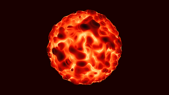 “Pyroclastic fireball” by Duke
Introduction
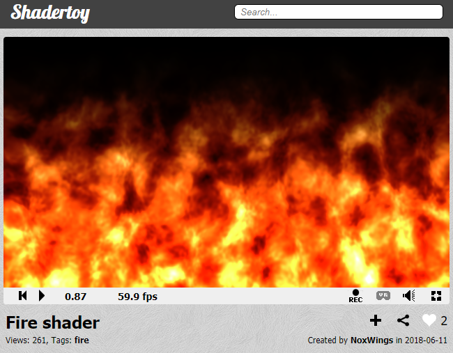
Today I’m going to look at one of the most basic things in shaders, the fire shader. We’ll look at the basic components of the shader, including random, noise, fbm, and bumpMap, and see how they can be represented in the fragment shader used in Shadertoy.
The code to analyze here is Fire Shader, which is simple but contains a lot of necessary information. The first time I saw this code, I was so happy that someone wrote the example code for me. So let’s get started.
random
In most programming languages, random functions can be loaded in a simple form and used immediately. In javascript, Math.random() returns a value between 0.0 and less than 1.0. In python, you can do the same with random.random() after you have loaded the random library with import random.
There is no such convenience function in shader. Instead, we have two options. One is to load an image with a random value (mainly black and white noise), and second is to write a random function directly.
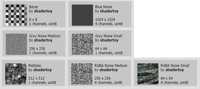 Shadertoy basically provides noise images. We can see these to press iChannel 0~4 at the bottom of the code and select Texture. I’ll cover that in another article.
Today, we will learn how to write random functions directly. We already have a lot of good explanations in this article of The book of shaders and this code and video, but I will try to explain it more easily and as easily as possible.
A random number is an unpredictable number that has no periodicity. Here, periodicity is a property in which the same number is repeated. Let’s take a look at the following sequence.
1, 2, 3, 4, 5, 4, 3, 2, 1, 2, 3, 4, 5, 4, 3, 2, 1, 2, 3, 4, ...
Here 1 is on the 1st, 9th, 16th. Assuming that this sequence continues, we can predict that the next one will be 1 in 23rd, adding 16 to 7. Numbers 1 through 5 are repeated and appear. In other words, this sequence is cyclic and not random because it can be predicted. If you create a password like this, you will immediately get caught by your opponent, and when you create a unique item drop table, most users will get unique items and the balance in the game will collapse.
So what about this sequence?
1, ?, ?, ?, ?, ?, ?, ?, 1, ?, ?, ?, ?, ?, ?, ?, 1, ?, ?, ?, ...
Here, ? the number shown is an unpredictable number. It would be nice if we could make this number, but 1 coming from the 1st, 9th, 16th, … is predictable. So what if the cycle of 1 is increased?
1, ?, ?, ...(A very large number of ?), ?, ?, 1, ?, ?, ..., ?, ?, 1, ?, ?, ...
We still see the periodicity, but the remaining numbers are almost “?”, so it will be a sequence that is almost impossible to predict. This is a random number generator that is commonly used on computers. Since a computer generates a random number using a formula, it is unavoidable to have periodicity, but it maximizes the cycle to produce a random number that is almost impossible to predict.
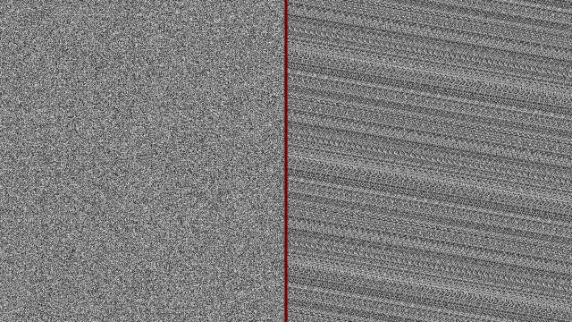
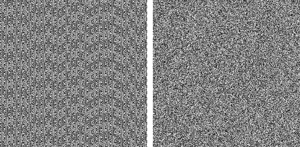 A comparison of the randomness created by PHP’s built-in functions (left) and the randomness generated by Random.org. You can see the pattern (periodicity) on the left. You can see that the quality of the random created by the right is relatively better. Source link
Now let’s look at how to create a random function (random number generator) in shader with code.
b = 78.233
c = 43758.5453
The origin of this function, float rand(vec2 co), is not yet known. Discussions related to this have been posted on the stack overflow, but they have failed to reveal the exact origins here. We do not know its origins but now it has become one of the most famous and widely used functions on the shader side.
If you set different values for a, b, and c while varying the range slider above, there may be a plausible random value, but sometimes there is a regular value as shown in the image below. We do not know what the original creator of this function originally set a = 12.9898, b = 78.233, or c = 43758.5453, but most people do not change this value. We can use this value as it is.
 The image when a = 3.244, b = 19.464, c = 44569.8166. In addition, you can see that when you set a, b, and c to 0 or set different values, random quality is sometimes bad.
This function simply creates a random value between 0.0~1.0 for each pixel in the 2D image. You can see that instead of using uv on line 8, we only used gl_FragCoord to calculate the random value. The float rand(vec2 co) function calculates a random value by putting a variable in the co place. Of course, we have already mentioned that this random value is a pseudo random value that can be predicted but has a long cycle because it is calculated as an equation.
dot means dot product, inner product, meaning that each component is multiplied and added together. For example, gl_FragCoord.xy and vec2(a,b) dot operations are equivalent to gl_FragCoord.x * a + gl_FragCoord.y * b. The result of a dot operation is always float.
sin is the trigonometric function we are continuing to encounter in this series. In Shadertoy - Metaball, sin is used to change the center coordinates of each meta ball. Again, sin changes the input value and makes it periodic.
Having a periodicity is a bad element at random, but if the cycle is very large, it is difficult to predict. This is the c that is multiplied by sin. Because 43758.5453 is a very large value, the cycle of the sin function also increases.
fract is the most important part of this function. fract is the abbreviation for fraction. Real numbers can be divided into integer part and fractional part, of which the fractional part is called fractional part in English. fract flushes the integer part and returns only the fractional parts. This function is opposite of floor in previous post.
Random page of The book of shaders has a very neat explanation for this. I tried to reproduce it by referring to a lot of this.
At first, we can see a plain y = sin(x);. Uncommenting the second line results in y = sin(x) * 5.0;. Notice that the slope of the function increases and the variation increases. This means that even if the value of x changes very little, the amount of change of y value becomes 5 times larger.
If we uncomment line 3, we can see that the value of sin(x) is limited to 0.0~1.0. This is because we left only a fractional part. If we uncomment line 4, we can see that the change is more irregular. If we continue to uncomment line 5 and line 6, we will notice that we can not predict exactly what the next value will be when we move one step to the right. We can get a random value by taking the fraction fract of the sin function multiplied by this large number.
noise
What is the difference between random and noise? In short, noise used in the shader has continuity around it.
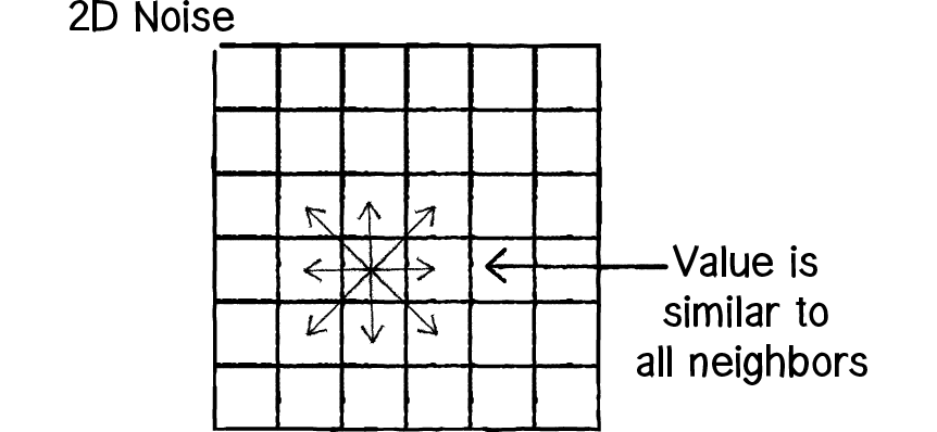 The value of noise has continuity to the surroundings. Source link
On the other hand, the random texture seen above has independent values regardless of its surroundings. As you can see above is because it should not be predictable. In the end, the task of creating noise randomly is to create a predictable noise with continuity with an unpredictable rand function.
In fact, the fire shader being analyzed here defined the rand function, but did not use it. The alternative is the hash function on line 4. Note that the rand function returns one output, so the return type is float, but the hash function returns two outputs in a similar structure, so the return type is vec2. And hash outputs between -1.0 ~ 1.0 compared to rand where the output between 0.0~1.0 is output. The reason is that we do not want to write the result of hash directly to gl_FragColor, but try to load it from another function noise.
Change the output of the hash function to 0.0 ~ 1.0, and only the first x value in color is the same as rand. If we uncomment line 12 and change the random value to y, we will see a little bit of the pattern in the image, but we can see that the numbers used to calculate y are not very good numbers. However, the results of the fire shader to be calculated later do not have much effect.
The following is about hash without sin. I will introduce related contents later in another article. If you want to see the contents of this article, I think it would be all right if you pass it.
If you look at the Shadertoy code Hash without Sine, when you keep it on, there will be a difference between left and right from 2 seconds later, and the difference increases gradually. When you continue to produce a random number, you can see that the result of using the
hashfunction on the left is much more stable than thesinfunction on the right. It is said thatsinis not a function designed for precise calculation, but there is a difference in calculation results for each GPU.
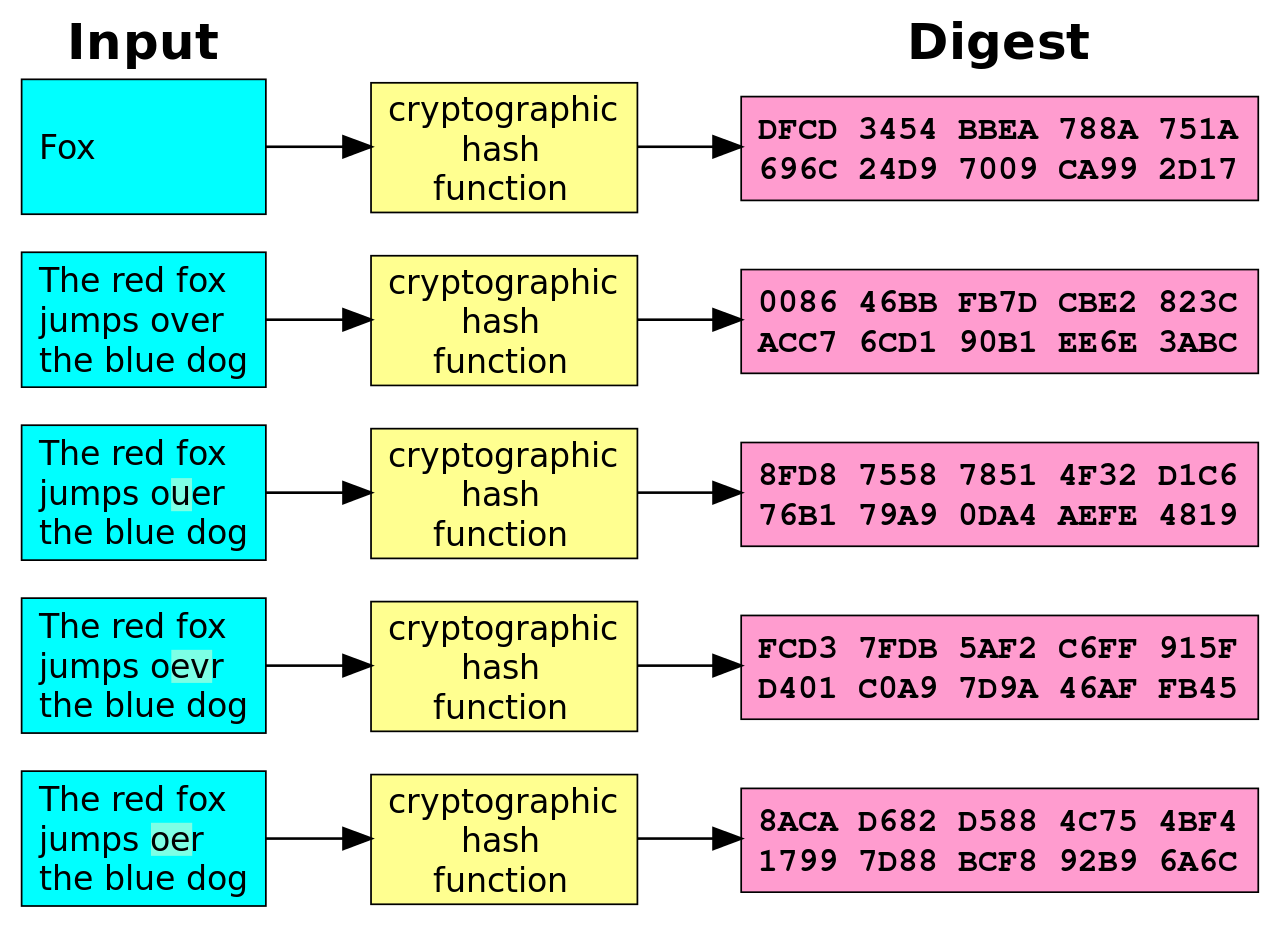
hashis the name of the function used for the original encryption. Any value you input will return output according to certain rules. The output is random and almost unpredictable. Assinreturns the same output as the cycle returns,hashhas the probability that any two inputs will produce the same output according to the rules of the function. This is called hash collision.
However, if this hash collision is unlikely to occur, the shader can use this function as a sufficiently random function.
In September 2017, Inigo Quilez introduced several fast
hashfunctions that do not usesin. These functions will be introduced in other articles.The
hashused in fire shader usessininstead. It is possible to change the function name torand2because it is misleading.
So what kind of function is noise used here? It was a very complicated code, but it was also the code that Inigo Quilez first wrote in Noise - simplex - 2D. And, according to this code, this function is calculating Simplex noise.
The first noise was created by Ken Perlin in 1983 and is called Perlin noise. In 2001, Ken Perlin released a version of Perlin noise that he created, which sometimes improved directional defects and computation speeds, which is Simplex noise.
In fact, the output of the two noises does not make much difference to the eye. In the code below, the left is Simplex noise(noise) and the right is Perlin noise(noise_p). Perlin noise, which we often think of, will be cloud-shaped. Here, adding the same noise while changing frequency, it becomes fractal noise like a cloud image that can be easily created in Photoshop. Fbm is an abbreviation of Fractal Brownian Motion and is a function that generates such fractal noise.
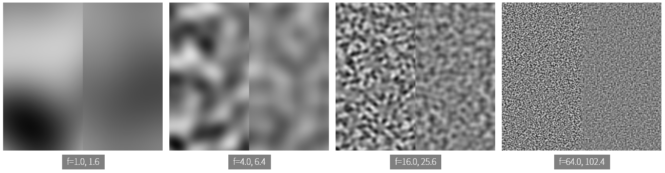
Have you seen multiplying uv in noise by 10. and 16. in line 47 and line 50, respectively? What if we change this number to 1.? What if we change it to a big number like 100.?
When you change to a smaller number, the image becomes blurred and the pattern becomes simpler. Conversely, if you change it to a larger number, it will look like a random texture with a poorly visible pattern. Here, a small number, a large number, can be thought of as the camera zoom in, zoom out. Multiplying a small number will zoom in on a small portion of the noise texture, and multiply it by a larger number to display a larger portion. Here, the number to multiply is called frequency. Frequency is the number of frequencies, ie, how many times a periodic phenomenon occurred during a unit of time. The smaller the frequency, the smaller the change. The larger the frequency, the greater the change.
The most important role of noise is interpolation. In other words, it smoothly connects between adjacent noise values. Perlin noise is a method of interpolating values between four adjacent vertices in a square grid. Simplex noise is a method of interpolating values between three vertexes of a triangle.1
If the frequency is small, the area to be interpolated is visible because the narrow area is enlarged, and as the frequency becomes larger, the interpolated area becomes almost invisible.
The noise texture is basically blurred because it is an interpolated image. The function fbm, which makes the detail of this image distinctive and makes the image like the photoshop clouds that we have seen a lot.
fbm
Noise image is blurry, so it is not practical to use it. This is complemented by fractal noise.
The left is the result of noise, and the right is the result of the fbm function. You can see that this is a much more detailed expression in fbm.
The code is simple, so let’s analyze it. The mat2 in line 28 is a float matrix with two rows and two columns. Here, the rotation transformation and the magnification transformation are multiplied. In other words, we can write this again.
The previous matrix is the rotation transformation, and the matrix after is the expansion transformation. Magnification is doubled because the unit matrix, \(\left[\begin{matrix}1 & 0 \\ 0 & 1\end{matrix}\right]\) is multiplied by 2, it turns out that the rotation is from \(\left[\begin{matrix}cos(\theta) & sin(\theta) \\ -sin(\theta) & cos(\theta)\end{matrix}\right]\) to \(cos(\theta)=0.8, sin(\theta)=0.6\), about 36.8 degrees.
On line 29-32, we add noise(p) to f, which reduces the coefficients by half to 0.5000, 0.2500, 0.1250 and 0.0625, respectively. In this case, the value added later becomes a value that is less influential.
And multiplies the conversion matrix just as you see with p=m*p;. Enlargement conversion is the same effect as enlarging the frequency seen earlier. Remember that as the frequency gets larger, it becomes a more detailed image that is hard to find patterns. Because the finer the image, the smaller the effect on the final result of the fbm function is, but the effect is negligible. The detail creates the difference between left and right.
In the last line 33, -1.0~1.0 will be output between 0.0~1.0. This is the output range that can be written directly to the color value.
For fbm, you might want to read Inigo Quilez’s application which puts fbm back on fbm to produce a better result. This part is also important, so I think we’ll have to deal with it later.
bumpMap
I am actually writing this article for a few days. I’m writing bumpMap now and it’s been 4 days since I started writing. It seems that it took me a while because my style of writing was clogged and I could not find it until I could find the material and move on to the next one. Since I have covered a lot of important things in the past, I think that the latter part can be passed quickly.
The word bump has the meaning of collision or hump. If the word bump is familiar in our lives, one of the bumper of the car will be. The bumper is a consumable part that absorbs shocks from the front and rear of the car.
The bumpMap function adds the detail of the surface as normal.2 normal is the direction vector of the surface facing away from the center of the object. Also known as normal vector. In fact, now that we are dealing with 2D, not 3D, the surface here is not really an overhang.
The left side is fbm, and the right side is normal, which is the calculation result of bumpMap. The image is generally bluish because it stores the x, y, z of the normal vector in the R, G, and B channels, respectively. x and y each have a value between 0.0 and 1.0, while in line 44 we gave z the value of 1.. So the image looks blue.
If we look at the rest of the code, we can see that the value of 1./resoultion.xy is stored in s on line 38 and vec2(1.,0), vec2(0,1.) is multiplied to that value on line 40-41. This shows that fbm is obtained for a point on the screen that is 1 pixel away from uv on the x axis and 1 pixel away on the y axis.
Line 43 gets the difference between the x-axis and the y-axis, then multiplies the predefined normalStrength to make normal strong. If we change this value, which is defined in line 1, we can see that the right image is blurred or intense. xy can range from -normalStrength to normalStrength but the actual value will be very small because the value of fbm changes slightly in successive intervals. That’s why it multiplies a large normalStrength.
Line 44 adds .5 to xy. Because .5 is the median. A smaller value than this indicates a negative direction, and a larger value than this indicates a positive direction.
Other effects
Let’s see how the normal computed above is actually used to create a fire shader.
normal computed by bumpMap is affected by time and is moving upward. Line 5’s distortionMovement has a y value of -0.3, so it moves up. You can change this value and change the x value.
Note also vec2(1.0, 0.3), which is multiplied by uv in line 52. Multiplying 1.0 will not change the value, but multiplying 0.3 will reduce the frequency. So, you will have an elongated image up and down.
Next, displacement was used. Unlike bumpMap or normalMap in 3D, this technique actually changes the shape of the 3D geometry. In 2D, it is used to produce wave effects such as those seen in Photoshop.
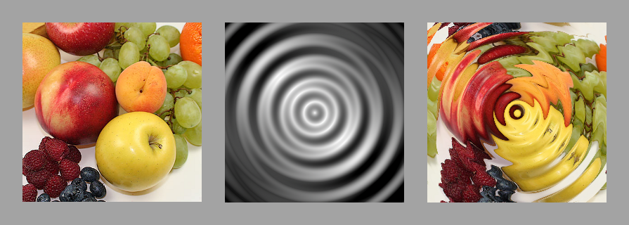
Putting the displacement here in gl_FragColor makes it clear what is happening.
The left side is normal and the right side is displacement. To display the color value, we changed the limited value between -1.0~1.0 to 0.0~1.0. It looks blurry but it looks like something is moving. If we give the distortionStrength to a large value such as 10.1, we can see that something is definitely changing.
If we look closely at line 57, we can see that bumpMap computation result subtracts 0.5 which was added to xy again. And then, clamp, which limits the output between the minimum and maximum values after multiplying by distortionStrength, uses a built-in function to limit the output to between -1.0 and 1.0.
If we come to this point, we can see that both bumpMap and normal explained in the previous section were the process of obtaining this displacement. There is nowhere else in the code where bumpMap and normal are used.
We need to look at the code a bit to see if displacement works properly. This is because displacement plays a role in fire texture rather than its own meaning.
Finally, images that are close to the fire texture have appeared. Line 54 adds displacement to uv, and line 56 computes uvT. It seems to be an abbreviation of uv Texture. Please note that the structure is similar to line 52. The value that multiplies y is 0.5, which creates an elongated image, and fireMovement also shows the speed of y up to -0.5.
If you change y of fireMovement to 0.5, you can see that the image is shuddered, because the displacement moves the overall coordinates upwards, but the image itself goes downwards, so we can see displacement better.
On line 57 we get the value fbm with frequency 8.0. I have already mentioned a lot about how changing this value has an impact on the image. The pow function is a built-in function that computes powers. Since the exponent is 1.0, the calculation is not different, but if you change the number, you can see that the image becomes darker or lighter. Values are between 0.0 and 1.0, so if the power is greater than 1, the value is smaller, and vice versa.
Finally, let’s look at the gradient and color that are involved in the intensity of fire.
On line 59, the pow built-in function that we mentioned earlier comes back. \(5 \times (1 - uv.y)^2\) has a value between 5.0 and 0.0 when uv.y is between 0.0 and 1.0, and has a larger value when y is smaller. On line 60, finalNoise is multiplied by n, so n has a larger value as y is smaller.
Line 62 multiplies finalNoise by the value to be the color’s coefficient. n is the output of fbm, so it has a value between 0.0 and 1.0. Therefore, we square the value, the smaller the value. Unlike the R channel, the G and B channels are squared so that the red color is emphasized.
You can now uncomment line 63 and comment out line 64 to see the final fire shader. Experiment with your own fire shader by changing the various variables shown here.
 fireMovement.y = 0.5, distortionStrength = 0.8, color = finalNoise * vec3(2. * n * n * n, 2. * n * n * n, n);
I’m going to finish the long fire shader analysis with this. Next time I will try to come back with a little bit easier and shorter code. Thank you for reading the long story.
-
It seems that there is a confusion in terms, so the
bumpMapfunction used here actually calculatesnormal. The originalbumponly determines the extrusion in the z direction with the intensity of the black and white image, while thenormalcomputes the extrusion in the x, y, and z directions through the RGB image. The originalbumpis not used at this time as the GPU speed has increased.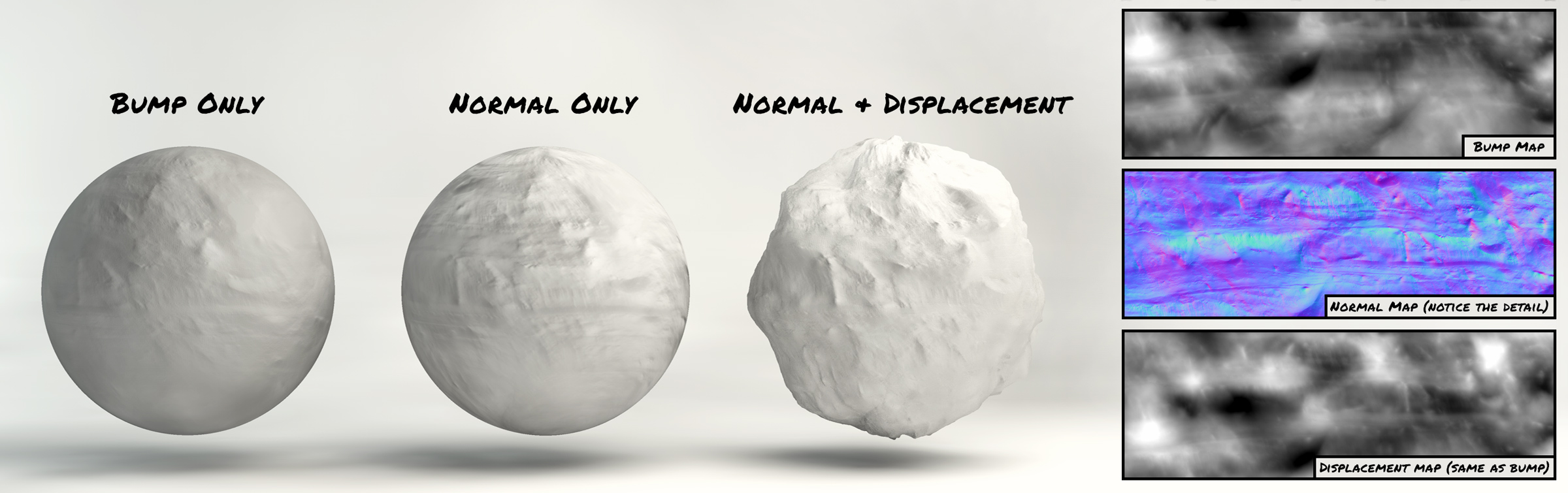 image link ↩