Shadertoy - Metaball
12 Dec 2018 • 0 Comments
Introduction
Following the last article, we will look at one of the most fundamental implementations of 3D graphics, the metaball. The idea of this posting is heavily dependent on Ryan Geiss’s this article. From his home page, he has been working on Google since 2010.
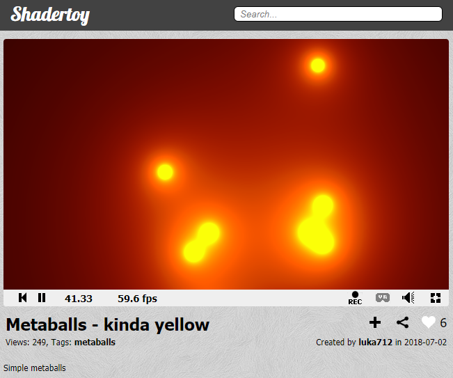
Shadertoy’s code to analyze today is the Metaballs - kinda yellow, which is a hard pick among many metaball implementations. I tried to find something that looked simple but beautiful visually. So let’s get started.
Coordinate base code
Prior to the full-scale content, here are some basic codes related to coordinates.
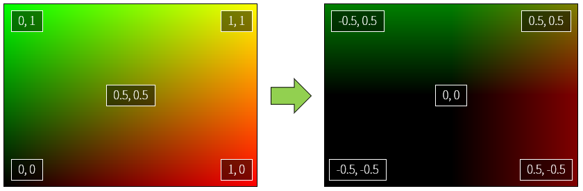
In the previous article, vec2 uv = fragCoord/iResolution.xy; is used to set the values of uv.x and uv.y corresponding to each pixel to values limits between 0.0~1.0. This code was also described as the boilerplate code most commonly used in Shadertoy.
However, lines 11 and 15 also have code that changes the default coordinates.
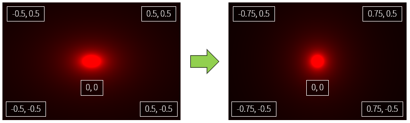
Line 11 : uv -= .5;
Line 15 : uv.x *= iResolution.x / iResolution.y;
First, let’s put the code to look at line 11.
The comment in line 5 has uv -= .5; appended. If you uncomment, you can see that the screen will become globally dark. You can guess that the range will be -0.5~0.5 because you subtract 0.5 from the uv.x, uv.y values in the range of 0.0~1.0 across the screen.
The color value of the shader is valid only from 0.0 to 1.0, and the rest is clipped. In other words, a negative number is calculated as 0.0, and a positive number greater than 1.0 is calculated as 1.0. As a result, the percentage of black on the screen has increased and the overall darkness has increased.
Notice that the coordinates in the center of the screen are now (0, 0) from (0.5, 0.5). This will make it easier to draw circles around the center of the screen. It is easy to understand if you think about coordinate plane to learn from junior high school first grade(in South Korea).
Then what is uv.x *= iResolution.x / iResolution.y; in line 15?
The circle function has been added, and I will explain this later. First uncomment line 10 and check the difference yourself. Do you feel the width of the circle is changing?
If we analyze uv.x *= resolution.x / resolution.y;, this expression is multiplies uv.x by (x size of screen / y size of screen). In general, the width of the monitor is usually longer than the height of the monitor, if you use the same ratio of width / height, it will be rendered in a distorted state like the circle in the original example. This equation has the effect of normalizing the ratio to make it look like 1:1 aspect ratio.
So now it’s time to talk about the circle function.
Circle function
Remember the circle equation?
\[x^2+y^2=r^2\]This expression can be expressed as a shader.
If you look at the circle function, the argument of circle function is uv. And distance is a built-in function used by the shader. As the name implies, you can get the distance between a vector and a vector. More information is given in the book of shaders distance with examples.
Since the center of the screen is (0., 0.), if you find the distance between this point and all the points, a circle area is created naturally. Because the definition of a circle is a set of all points with the same distance from one point.
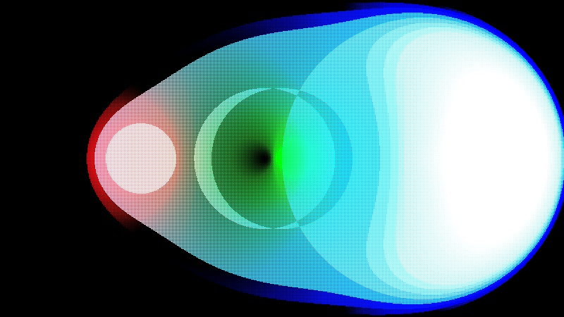
Here we put the distance information into the R channel of gl_FragColor. As a result, the farther away from the origin, the brighter the red. Use the step function if we want to clearly separate the circle’s area. This function returns 0.0 if the second argument is less than the first argument, and 1.0 otherwise. In the step page of The book of shaders, the first argument is named edge.
Uncomment line 5 to see the result of writing the step function. You can see that there is a circle with a clear borderline. All values less than 0.2 will be 0.0, otherwise all will be 1.0.
vec(0., 0.) acts as the center of the circle. In other words, if you change this value, the center of the circle changes and you can move it in parallel. The circle function in the second example in this article uses the center of the circle as the pos argument.
However, when we usually draw a circle, we often wonder about the inner area than the outer area. In other words, the inside is painted and used as a circle, and the remaining empty space is ignored. How do we do this? If you divide the two sides by \(x^2+y^2\) in the previous circle equation, you get:
\[1 = \frac{r^2}{x^2+y^2}\]If we take root on both sides of this equation, the denominator of the right term will be \(\sqrt{x^2+y^2}\). This expression is a value indicating the distance from the origin (0,0) to (x,y). The shader can be abbreviated with the built-in function distance. And if you put the pos argument in place of the origin (0,0), it will be the circle function you saw in the second example. The part that corresponds to the numerator on the right hand side is root, so \(r^2\) to \(r\), which is the radius of the circle. The second example uses 0.05.
float circle(vec2 uv, vec2 pos) {
    return 0.05/distance(uv, pos);
}
In the code below, the G channel also has a value, so you can see the same color combination as the original Shadertoy code Metaballs - kinda yellow.
It looks aesthetically better than simply marking the area with the step function. You might be able to find better results by experimenting with different color assignments.
Comment out the line 11 and uncomment line 12 to see a simple animation with the center of the circle moving. Remember the first time you used the time variable to change the color? If you insert the time variable in the center of the circle, the center moves as the center coordinates change with time. Normally put x=cos(time), y=sin(time), it does not matter even reverse as a source code.
So let’s move on to the next section. More than half came.
Add multiple shapes
We have drawn one circle, but how do we express two or more circles? It’s incredibly easy on the shader. Just add the color.
In the original code we first defined a circle in the float variable c with the circle function, and then added another circle function to c.
float c = circle(uv, vec2(sin(time * 2.) * .4,  cos(time * .4) * .4), r);
c += circle(uv, vec2(sin(time * .5) * .4, cos(time * .7) * .4), r);
c += circle(uv, vec2(sin(time * .7) * .4, cos(time * .8) * .4), r);
...
The result is several circles added as we can see. Let’s see if it really works.
The results are good. But wait a minute. Is not the center circle a little big? Is it an optical illusion? What about trying to get closer to each circle’s coordinates to see the results? The results are shown below.
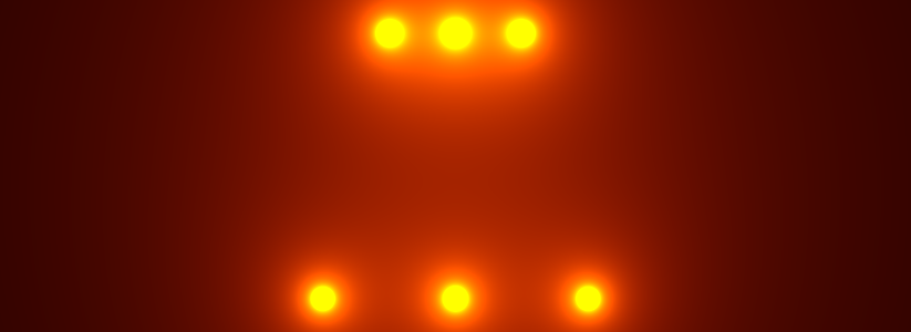
The upper circle is a little closer than the bottom. The more closely you place it, the larger the circle becomes.
This is because the circle in this code, and thus the meta-ball formula, is not a simple circle, but an influence on the surroundings.
Metaball
Ryan Geiss, mentioned in the first part of the post, writes about Metaboll:
The function [f(x,y,z) = 1.0 / (x^2 + y^2 + z^2)] might look familiar to people who’ve studied physics. This is the equation for the strength of the electric field due to a point charge at the origin. … The electric field is infinity at exactly the point where the charge lies, and drops off quickly as you go away from the charge. But no matter how far away you are from that point, it still has some contribution.
The metaball formula can be seen to be the same as the electric field strength around a point, and the part close to the metaball(circle) will have a very strong influence, but the point far from the center has some influence.
Ryan Geiss uses the band to make it easy to see where the influence come together. We can do it also.
On the sixth line, we use the function floor in the return floor(r/distance(uv, pos) * 5.) / 5.;. floor is a step function that removes the decimal point from a real number. It acts like int() in python, Math.floor() in javascript.
If you use this function, all the values that the metaball will make primarily will be one of 0, 0.2, 0.4, 0.6, 0.8, 1.0. When meta balls overlap, you can see that these values are merged and changed. Especially when they overlap, you can see that the size of the yellow circle increases. This is because the area where the summed value becomes 1.0 or more is increased.
I have moved all the rest of the code also. If you uncomment line 5, it looks like original. It is interesting to see what part of fragment shader in three.js differs from the original.
This concludes my second shadertoy code analysis. Next time I will come back with some more interesting code. Thank you for reading the long story.